Coordinate Systems
From high-school maths, you should be familiar with the cartesian coordinate system, and how to denote co-ordinates in the 2D plane, using (x, y) coordinates.

Figure 1: 2D cartesian coordinate system, by Kbolino, Public domain, via Wikimedia Commons
The same principle can be extended to 3D, with (x, y, z) coordinates.
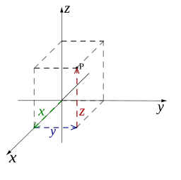
Figure 2: 3D cartesian coordinate system, by Cronholm144, Public domain, via Wikimedia Commons
With 3D coordinate systems, you should be aware of whether coordinates are right or left handed. In this course, we will use right handed coordinates exclusively.

Figure 3: Right handed coordinates, thumb=X, index=Y, middle=Z, by Abdull, CC BY-SA 3.0, via via Wikimedia Commons
In medical imaging in general, and in particular, in image-guided surgery, it is important, not to flip axes around. Software must not accidentally mix up, the left and right hand side of the patient, which in many parts of the anatomy look very similar. So, do not switch left/right handed coordinates, without a lot of software testing.
Image-Guided Surgery (IGS) Systems
Each image-guided surgery system will have a set of coordinate systems. It is essential to know how to convert coordinates from one coordinate system to another. For example, in the SmartLiver laparoscopic liver surgery application, there is:
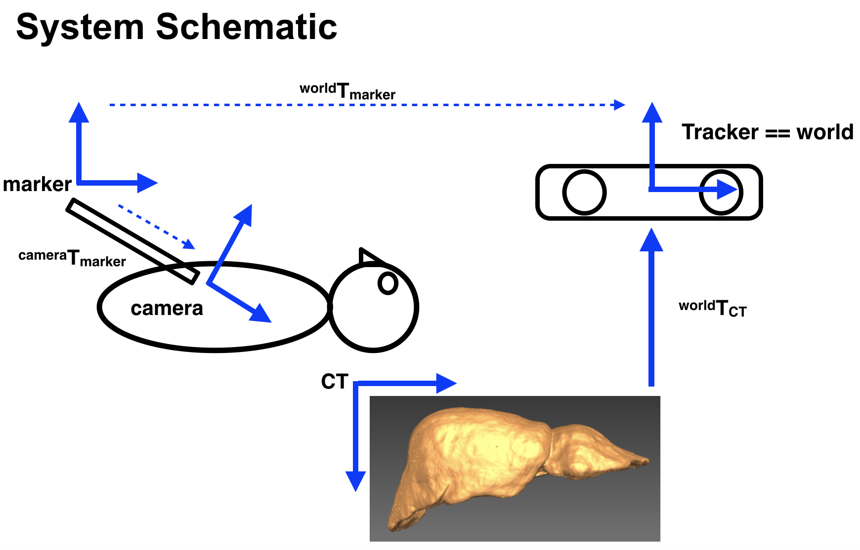
The different coordinate systems are:
The 3D CT image = CT
The video camera = camera
The tracking markers on the end of the laparoscope = marker
The tracking system = world
Converting Coordinates
Let a transformation be denoted by  , where is a
  matrix:

where  is a
is a  orthonormal rotation matrix, and
  a
a  translation vector.
Then the transformation of coordinates from coordinate system  to coordinate system
  is given by:

where  is a 3D point, in coordinate system , represented as a
  column vector using homogeneous coordinates, and
  represents the location of the same point, in coordinate system .
Worked Example
So, using the laparoscopic liver surgery system above, an anatomical structure such as the liver can be represented as a set of triangles, which comprises 3D points, and their edge connectivity. This coordinates of this triangle mesh can be converted to video camera coordinates thus:

where
 registers CT coordinates to world (tracker) coordinates
 is the inverse of the
  which is obtained from the tracking system
 is given by calibrating the pose of the video camera with respect to the tracking marker
# Conclusion
So, the main technical idea behind many IGS systems are to take:
image data, in this example, we used a triangle mesh representing the liver, derived from CT
tracking system, tracking markers
computer
and correctly calibrate/register/track so that the image data can be displayed in the correct coordinate system. The core idea is geometrical.
However, the real science/art is in designing the calibration and registration procedures so they can be performed in a reasonable time-frame by clinical staff, without impacting the clinical workflow, to the benefit of the patient.