4. Augmented Reality (AR) Overlay
4.1. Introduction
This is the SciKit-Surgery tutorial on augmented reality image overlay. It was developed as a tutorial for online delivery during the 2020 Medical Imaging Computing Summer School hosted by UCL.
The tutorial is divided into four sections:
Background material (30 mins)
Exercise 1 - 3D Model Alignment (15 minutes)
Exercise 2 - 3D & 2D overlay on video feed (15 minutes)
Exercise 3 - AR Demo (10 minutes)
4.2. Learning Objectives
After completing this tutorial, students should be able to:
Describe common uses of image overlay in medical imaging.
Describe common challenges of image overlay in medical imaging.
Explain the advantages/disadvantages of overlaying 2D & 3D data.
4.3. Assumed Knowledge
It is assumed that pupils have a working Python installation and are able to install packages. If this tutorial has been installed as part of the MPHY0026 module, then the required packages should already be present.
4.4. Background
Overlaying data on a video feed is commonly used to:
Present additional textual information to the user.
Highlight areas of interest in the image.
Implement augmented reality (AR)
Figure 1. Illustration of text overlay on a video image, taken from the Terminator movies, available on YouTube.
Head mounted systems for overlay, such as the Microsoft Hololens, allow for overlay directly in the user’s field of view.
Figure 2. Illustration of proposed medical application of Microsoft Hololens see through head up display, available on Microsoft’s Hololens channel on YouTube.
For surgical applications, specific use cases include:
Drawing a region of interest around pertinent landmarks - tumors, arteries etc.
Overlaying a 3D model of an organ which includes additional anatomical information that may not be visible on the video.
Picture in picture ultrasound, so that a surgeon does not have to look between multiple screens.
4.5. Issue to consider
Where to place the overlay data? Data should be conveniently located, but don’t want to obscure the clincian’s view.
How is the AR model aligned to the real life view? Manual alignment is simple to implement, but can be difficult to orient properly for complex shapes (See exercise).
Getting things to look ‘real’ is challenging.
4.6. Additional information
Further learning material can be found in the following sections of this course.
Augmented Reality - examples of different systems and use cases.
Graphics - Technical details on different rendering methods and algorithms.
4.7. Exercise 1
Running the overlay application will allow you to try manual alignment of 2D/3D objects. Once you have followed the Python Setup, then from the root MPHY0026 folder, run:
python mphy0026_overlay.py
Controls for controlling the model: * Moving model: Shift + click + move mouse about * Change model scale: zoom in/out OR control + click + move mouse up/down * Free body rotation: click + move mouse about
Two cases are presented, a 2D alignment of a circle, and a more realistic example where a liver model needs to be aligned to a background shape.
In each case, try to minimise both the size error and the alignment error. Alignment error in this case in an arbitrary measure that considers both rotation and position.
Repeat the exercise multiple times (Press ‘Move Target’ to generate a new location).
Does adjusting the opacity of the model make it easier/harder?
How does 3D alignment compare to 2D aligment?
What are the potential drawbacks of this approach for surgical applications?
What can be considered a ‘good’ aligment?
What type of user interface would be best for aligment?
4.8. Exercise 2
The next application shows a more realistic use case, where we want to overlay 3D and 2D data on the same scene. A webcam is required for this section.
python mphy0026_slice_overlay.py
Here, we overlay a 3D model of an artificial skull, along with 2D slice data taken along a plane of the volume, on a video feed. The two sliders can be used to control the position of the 2D slice. The model/slice views can be toggled on/off.
Try to overlay the model on your own head/a friend.
What are the potential drawbacks of this approach for surgical applications?
Which of the two views - 3D or 2D, do you think could provide the most useful information to a surgeon?
4.9. Exercise 3
The final application will demonstrate a more realistic use case, where we will combine some of the work done in previous chapters, to visualise our own ‘probe’. This exercise requires you to have completed the Camera Calibration workshop, and have access to the config file and saved calibration data.
Using a calibrated camera and a chessboard, it is possible to estimate the pose (position & orientation) of an object in 3D space. We can use this pose information to overlay data in the correct position in 3D space:
python mphy0026_chessboard_overlay.py -c doc/summerschool/camera_calibration/video_calib_chessboard.json
Remember to change the “calibration directory” and “calibration prefix” in the config file to what you have set for your camera calibration.
Here, we have overlaid the video feed back onto the chessboard pattern. As you move/rotate the chessboard, the overlay should remain in the same position.
As with the SummerSchoolPivotCalibration tutorial, tracking a tag, or a chessboard computes the position of the tag/chessboard with respect to the camera. This is similar to the process of positioning a CT scan in front of a virtual camera, as described in the tutorial on coordinate systems.
Such approaches can be used with an ultrasound probe, that is either external to the body, and tracked by optical tracking for example, or internal to the body and tracked by computer vision from a surgical video feed like a laparoscope. In both cases, the ultrasound image can be displayed relative to the tracked probe.
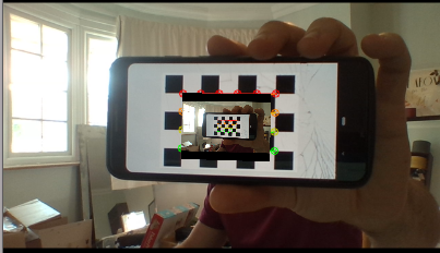
This is illustrated below, but using a mobile phone as a pretend probe. The probe is tracked by a laptop webcam. So, the position of the “probe” (i.e. phone) is known relative to the camera by computing the pose of the chessboard relative to the video camera. If we know the position of the “ultrasound” image relative to the same chessboard, we can display the ultrasound in situ. This is achieved by the process of Handeye. In the example below, instead of using actual ultrasound, we just re-use the same video feed.
python mphy0026_chessboard_overlay.py -c doc/summerschool/camera_calibration/video_calib_chessboard.json -o 90
Once again, remember to change the “calibration directory” and “calibration prefix” in the config file to where you have saved your camera calibration.
Here the offset of the ultrasound relative to the origin of the tracked marker (a chessboard), is 90mm in the x direction. You can adjust this value to get the best results on whichever phone/chessboard you are using.
In practice, instead of an offset of 90mm in one axis, you would provide a full 6DOF transformation (rotation about x, y, z axis, and translation along x, y, z mm), and potentially a scaling transformation (scaling in x, y) to get the right pixel size of the “ultrasound” image, via Handeye.
4.10. How Does The Overlay Window Work?
There are very few examples of a Python/VTK render window on the internet. The usage of scikit-surgeryvtk’s VTKOverlayWindow is documented here, with links through to the actual code.